As the electric vehicle (EV) industry pushes toward 800V architectures and higher power densities, the traction inverter—the heart of the electric powertrain—has become a significant thermal bottleneck. With the widespread adoption of Silicon Carbide (SiC) MOSFETs, inverters are operating at higher switching frequencies and higher efficiencies than ever before. Yet, these advancements concentrate heat flux into smaller silicon footprints, pushing conventional single-loop cooling systems to their physical limits. For high-performance traction inverters, the transition to a dual-loop cooling architecture is no longer optional; it is a fundamental design requirement for thermal stability and peak performance.
1. The Thermal Limit of Single-Loop Architectures
Traditionally, many EVs utilized a single coolant loop to manage the battery, motor, and inverter. While this simplifies the Bill of Materials (BOM), it creates a fundamental thermal conflict. The lithium-ion battery pack typically requires a narrow operating window (20°C–35°C) for optimal health and longevity. In contrast, power electronics—specifically SiC-based inverters—can handle significantly higher temperatures.
When forced to share a loop, the inverter is often “over-cooled” to keep the battery within its desired range, or the battery is subjected to sub-optimal temperatures during aggressive driving to manage inverter heat. This compromises both system efficiency and the ability to sustain peak power delivery.
2. Architecture Breakdown: The Dual-Loop Philosophy
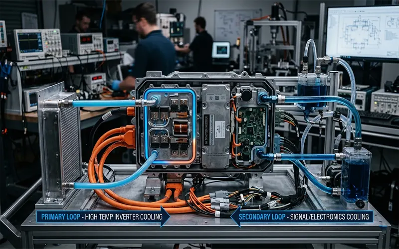
A robust dual-loop thermal management system decouples these components into two distinct circuits:
- Low-Temperature (LT) Loop: Dedicated to the battery pack. This loop maintains a steady, narrow temperature range, prioritizing the chemical stability and longevity of the cells.
- High-Temperature (HT) Loop: Dedicated to the power electronics (inverter, DC/DC converter, onboard charger) and often the traction motor. By separating this loop, engineers can allow the coolant to reach higher temperatures (e.g., 60°C–80°C) without affecting the battery, utilizing a dedicated radiator to dump heat into the ambient air.
This decoupling allows for “thermal zoning,” where the powertrain can push its thermal limits during rapid acceleration or track modes without risking the battery’s state of health (SoH).
3. Thermal Management Challenges: Heat Flux Density
The primary challenge in modern inverter design is heat flux density. SiC MOSFETs routinely generate localized heat flux exceeding $100 \, \text{W/cm}^2$. Managing this requires minimizing the thermal resistance ($R_{th}$) between the power semiconductor junction ($T_j$) and the coolant.
If thermal resistance is too high, the junction temperature rises rapidly during transient loads, leading to thermal cycling fatigue. In high-performance applications, maintaining a low and stable $T_j$ is critical to preventing premature component failure and ensuring the inverter can output its rated peak power for extended periods without derating.
4. Design Optimization Strategies
To extract maximum performance, the design of the inverter cold plate must be highly engineered:
- Advanced Cold Plate Geometries: Moving away from simple cavity designs, engineers now utilize micro-channel or pin-fin structures. These geometries increase the surface area for heat transfer and promote turbulence in the coolant flow, significantly enhancing the heat transfer coefficient ($h$).
- Flow Routing: The choice between parallel and series routing is vital. Parallel routing provides each power module with fresh, cool fluid, ensuring uniform cooling across all three phases of the inverter. Series routing, while simpler, results in the final module receiving “pre-heated” coolant, leading to temperature imbalances.
- Material Selection: Corrosion resistance is paramount, especially when using ethylene glycol-water (EGW) mixtures. Engineers must select cold plate materials that prevent galvanic corrosion and ensure that the coolant chemistry remains stable over the vehicle’s 15-year lifecycle.
5. Predictive Control Strategy
The physical hardware is only as good as its control logic. Modern Vehicle Control Units (VCUs) employ predictive thermal algorithms. Instead of reacting to temperature spikes, the VCU uses input from the driver’s pedal demand, navigational data, and environmental sensors to anticipate heat generation.
By dynamically modulating pump speeds and electronic valve positions, the system can “pre-cool” the inverter modules seconds before a planned heavy acceleration event. This proactive thermal management prevents localized hot spots before they occur, allowing the vehicle to maintain peak torque output for longer durations than a reactive system could permit.
6. Future Trends: Toward Immersion Cooling
While liquid-cooled cold plates are the current gold standard, the industry is already exploring the next frontier: dielectric immersion cooling. By submerging the SiC power modules directly into a non-conductive dielectric fluid, the thermal interface resistance is nearly eliminated. This technology is currently being prototyped for ultra-high-performance vehicles where power density is the only metric that matters.
For high-performance EVs, the dual-loop cooling system is the bridge between theoretical power potential and real-world sustained performance. By decoupling thermal requirements, optimizing cold plate micro-geometries, and employing predictive control logic, engineers can maximize the performance of SiC-based inverters while ensuring the longevity of the battery pack. As the industry moves toward 800V and beyond, thermal management will remain the primary enabler of the next generation of electric mobility.